December 10, 2016 Presentation
by Mark G.
I hope to be able to give you a fairly complete description on how to build a musical, brightly lit, small-scale Christmas tree. By small-scale, I mean that the tree can be placed on top of any side table easily, as it is about 12″ around by about 19″ tall. It requires one standard 110V outlet for power.
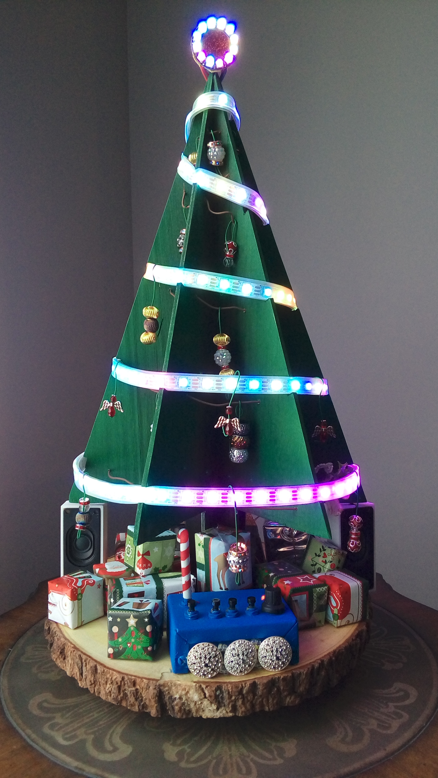
Here is a picture of the project at completion:
Arduino
The heart of the tree is an Arduino Uno (rev 3) micro-controller. The Arduino company is the original designer and custodian of the arduino ecosystem and provides technical details about the controller used.
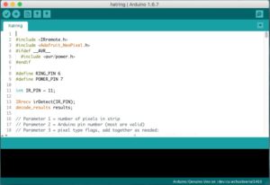
The arduino doesn’t run a full-fledged operating system like the Raspberry Pi. Instead, you use the arduino integrated development environment (IDE) to write and place a single program on the device. The IDE looks like this:
The programming language used for arduino programs is C++. This language can be very complex in some circumstances, but for the purposes of most arduino projects, it can be very straightforward. For example, here is a program to blink the built-in LED once a second:
/*
  Blink
  Turns on an LED on for one second, then off for
  one second, repeatedly.

  Most Arduinos have an on-board LED you can
  control. On the Uno and Leonardo, it is
  attached to digital pin 13. If you're unsure
  what pin the on-board LED is connected to on
  your Arduino model, check the documentation at
  http://www.arduino.cc

  This example code is in the public domain.

  modified 8 May 2014
  by Scott Fitzgerald
*/

// the setup function runs once when you press
// reset or power the board
void setup() {
  // initialize digital pin 13 as an output.
  pinMode(13, OUTPUT);
}

// the loop function runs over and over again
// forever
void loop() {

  // turn the LED on (HIGH is the voltage level)
  digitalWrite(13, HIGH);
  delay(1000); // wait for a second

  // turn the LED off by making the voltage LOW
  digitalWrite(13, LOW);
  delay(1000); // wait for a second
}
That’s it! Note the similarity to a python script on the Raspberry Pi. To send that program to the micro-controller, you must plug the arduino device, using a typical USB cable, into an USB port on your development system. Programs created in the arduino IDE are called sketches and have a file extension of .ino (dot ino). The above sketch would be saved as blink.ino on the host computer.
Sending the code to the controller is as simple as clicking the Upload button, which causes the C++ program to be compiled, thereby converting it to the machine language of the arduino micro-controller. It loads the machine instructions into the arduino’s memory over a serial connection (via USB) and then resets the board to start the new program.
The size and complexity of any given sketch is limited by the amount of memory on the micro-controller board (32kB code, 2kB RAM, 1kB NVRAM for the arduino uno). As you will see, though, a good deal of functionality can be packed into a small device.
I created a C++ class for the musical tree object so I could encapsulate the various behaviours and simplify the main sketch.
Source code: MusicTree.h (7.0 KB) MusicTree.cpp (13.4 KB) musictree.ino (5.4 KB)
The Electronics and Circuit
The electronic composition of the tree’s circuitry is not overly complex. This is mainly due to the encapsulation of all the complexity in three separate parts.
- Adafruit Music Maker MP3 shield with amplifier.
- Adafruit Neo-pixel strip and ring.
- Mini-breadboard for tying all the controls together.
A fine open-source software resource for documenting a circuit is called Fritzing (![]() ).
).
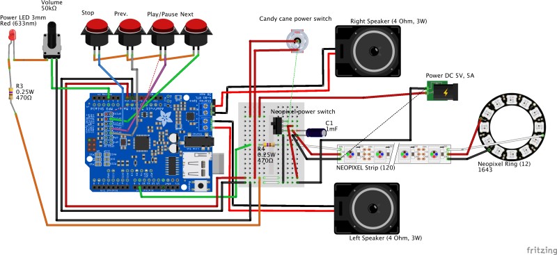
I used this software to create the following circuit image / breadboard diagram:
It must be noted that the actual arduino board is underneath the music maker shield and is not seen in the image. The use of shields allows for stacking of useful circuits on top of the base arduino board. This is much the same as a ‘hat’ for a Raspberry Pi.
The Fritzing software also had a neat feature wherein you could create a bill of materials (BOM) based on the parts that were included in the breadboard diagram. It is important to note that the BOM created is not accurate for the actual parts that I used in the tree. The choice of components in the Fritzing parts bin is varied and excellent, but it certainly didn’t have the exact parts I used.
A further item to note is that the Adafruit web site has a Fritzing library for the majority of the products they sell. This is where I retrieved the arduino, music shield, neo-pixel ring and neo-pixel strip parts for the Fritzing breadboard diagram.
The Structure and Mechanics
The attached README has some supplemental information about how the item was built: README.txt
Wooden Base (the Burl)
Here is a picture of the wood burl I used as the base of the tree. I found it at Homesense:
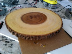
It has four small legs that give it about 1/2 inch clearance. In the finished product, I run the wires underneath it through holes drilled into the bottom of the enclosures and through the bottom of the burl.
I drilled a 1 inch diameter hole in the centre of the burl to hold the trunk of the tree.
Enclosures
Two enclosures were used, one to house the electronics and one to contain the control switches that operate the tree. The enclosures were positioned on the base as shown in the next photo:
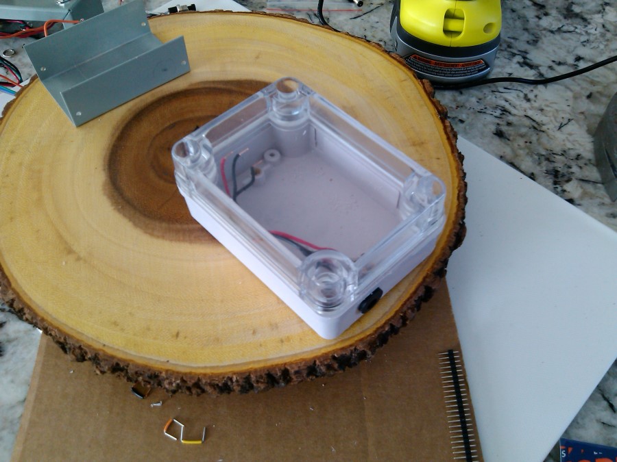
Arduino and music shield enclosure
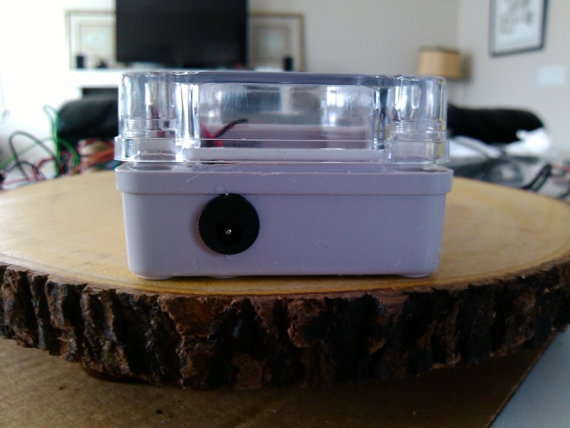
The plastic enclosure showing the power jack:
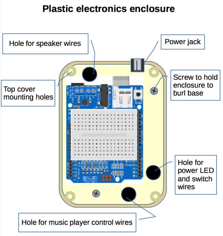
The hardware was fitted into the plastic enclosure as shown in the next illustration. The circuit boards were not fastened to the enclosure in any way. This was to enable the boards to be easily lifted up for programming or SD card replacement. This is not ideal, and a properly designed case which exposes these ports would be better.
The electronics enclosure was eventually covered with folded construction paper that was gold coloured with sparkles (a small Christmas gift bag was cut apart for this purpose).
Power and music control box
The controls for the tree fit in a metal control box in front of the tree. One wood screw was used to mount the box in place and only a single hole was required for wire routing. There are four push buttons, a rotating potentiometer, a toggle switch and a red LED.
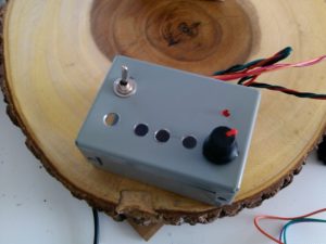
The red LED is used to indicate that power is on.
The rotating potentiometer is for controlling the volume of the music. It acts as a voltage divider and is connected to the arduino’s analog pin number 2. It is sampled each time through the program’s loop and the volume is set accordingly.
The toggle switch is a single pole, double throw (SPDT) and provides power when toggled forward, and no-power when toggled towards the back of the tree.
The four holes shown in the metal box are for each of the push button controls. From the left, the controls are STOP, PREVIOUS, PLAY/PAUSE, and NEXT. Songs are stored on the SD card as numbered files: 0001.mp3, 0002.mp3 … 0144.mp3. The current playing song number is stored in NVRAM (EEPROM) so the listener can resume playback at the same point when power is reapplied.
The STOP button causes the music to stop playing a song and to reset the song to play from the beginning if play is subsequently pressed. The PREVIOUS button stops the current song, decrements the song number and plays that song. The NEXT button stops the current song, increments the song number and proceeds to play that song. When PLAY/PAUSE is pressed, if a song is currently playing, it is paused, and another press of PLAY/PAUSE resumes the song at the point it was paused. If the PLAY/PAUSE button is pressed after the STOP button was pressed, playback starts st the beginning of the current saved song number. This logic is represented in the software.
Fasten all the buttons in place and solder all wires to their terminals on the push buttons, toggle switch, and volume control. Make sure to solder the LED, its resistor and the volume control’s plus tab in series and cover the bare wires with shrink-wrap throughout. Use fairly long lengths of wires to start, and cut them once you have routed them through the metal box hole, underneath the burl, and then up through the electronics enclosure holes.
The metal box was painted a festive blue colour using basic water-colour paint, and given a small decorative facing. The power toggle was covered with a candy cane fashioned out of white plastic and painted with a red stripe.
Tree / Branches
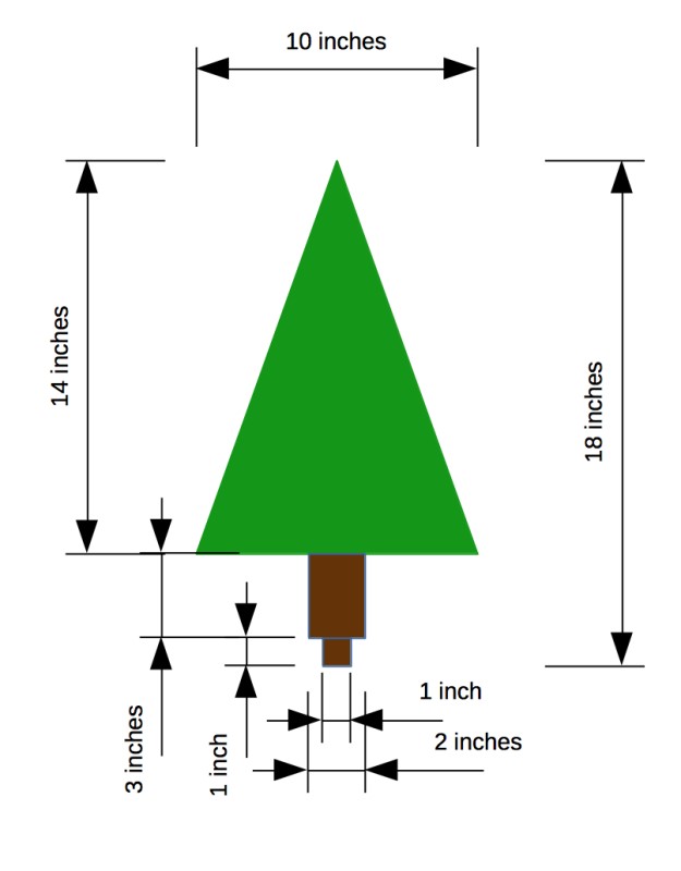 The wood chosen was 3/16 inch thick baltic birch that was 2 feet by 4 feet. The dimensions of a branch are shown in the next illustration. There were 3 pieces cut which allowed for a tree with 6 “branches”.
The laser cutter at Victoria MakerSpace was out of commission, so I had to cut the wood pieces for the tree branches by hand.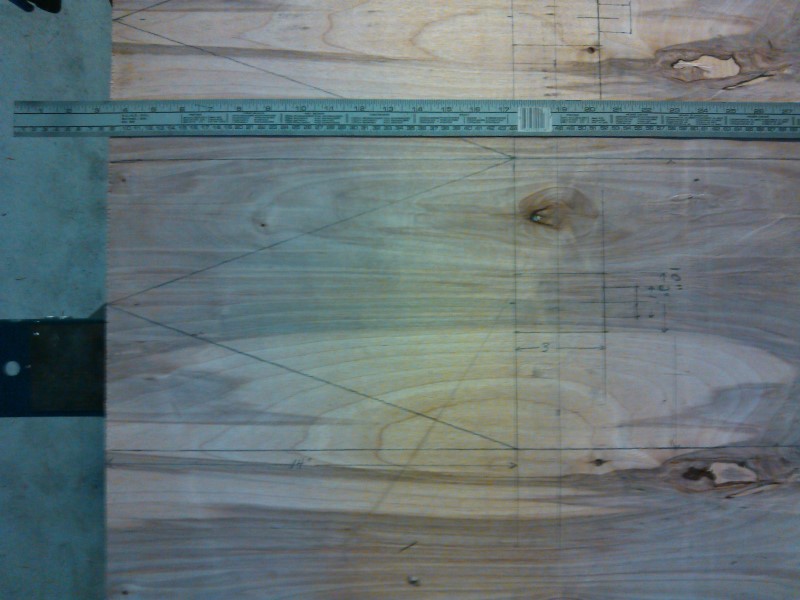
Each triangle had a different slot configuration. These slot lines can be seen in the following template image:
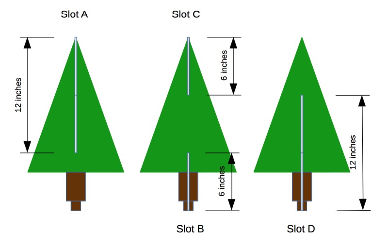
One had a 12 inch slot from the top, down to 2/3 of the height (Slot A), another had a 12 inch slot from the bottom, up to 2/3 of the height (Slot D), and the third had a 6 inch slot from the top, down 1/3 of the height (Slot C) and another 6 inch slot from the bottom, up to 1/3 of the height (Slot B).
I used a circular saw for the 18×10 rectangular cuts, then routed the slots according to the slot diagram (above), and finally, a jigsaw for the final shaping of the trunk cuts and branch angles.
It was important to cut the three 18 inch by 10 inch rectangular pieces first, before shaping the triangle branches and trunks. This is so I could use the router table and guide rail to make super-straight slot cuts. If the slots aren’t perfectly straight and the correct size, the branches will not fit together properly. The router had a 1/4 inch bit, so the slot width was also 1/4 inch.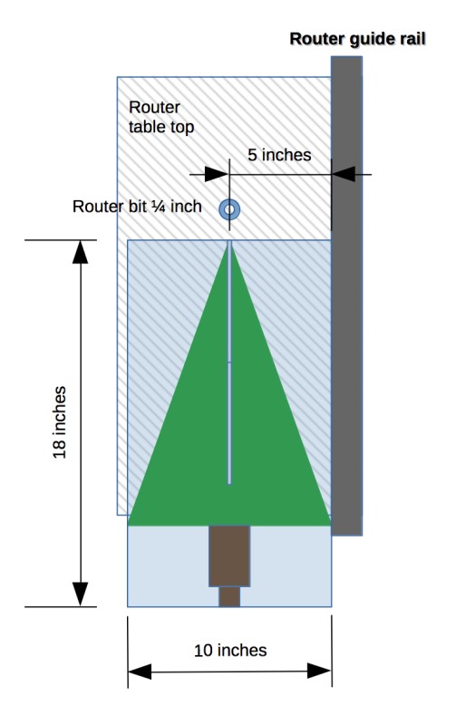
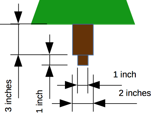
The trunk was 3 inches long and 2 inches wide (centred) with a 1 inch stub for anchoring in the 1 inch hole drilled in the burl:
Once the pieces were cut, they were spray painted brown (trunk) and green (branches).
To assemble, slide Slot B into Slot A until the trunk bottoms are even, then slide Slot D into Slot C. It’s not as hard as it sounds.
Once the tree branches are together, make them evenly spaced (you can create some wooden spacer triangles for this) and force the tab part of the trunk (the one inch section) into the burl’s one inch hole. The fit should be tight so as to use friction to hold it in.
An important consideration is to cut notches in the edges of the branches so as to hold the neo-pixel strip in place. A dremel tool was used to do this, and the notches were cut in a spiral-up pattern. The methodology used was to fasten the neo-pixel strip, using a clamp or binder clip, to one of the branches at the rear of the tree, near the plastic enclosure. The strip was then wound up around the tree in such a manner as to evenly spread all the LEDs. Five and a bit turns was about right. A black marker was then used to mark all the spots on each branch edge where the neo-pixel strip made contact so as to indicate where the notches were to be made.
Place green shrink-wrap tubing over the speaker wires and then run the speaker wires from the top of the burl, through the gaps in the tree branches, underneath the burl and then up through to back plastic enclosure. Connect the speaker wires to the music shield’s blue connector blocks.
Final Steps
Proper molex style connectors were attached to the neo-pixel strip and ring so as to facilitate disconnection and reconnection. This is preferable to soldering them together. I had to purchase a crimper and tool set to work with these male-female connection sets. I choose four wire connector pieces and bought a fair number of them for future use.
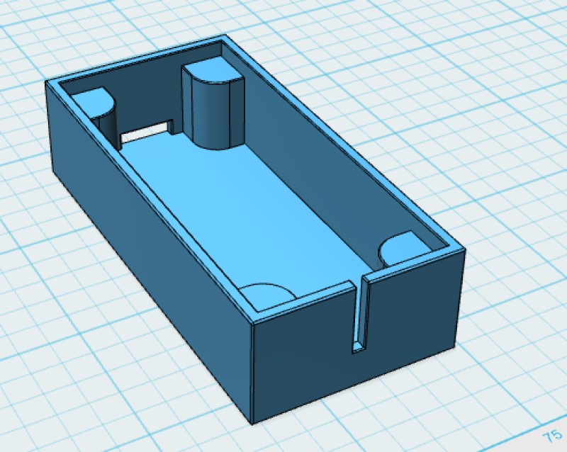
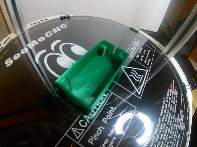
I created a 3D printable speaker housing. There are two files in this zip archive, the first is the 3D design for the speaker box in autodesk format, and the second is the printable STL format file for the speaker box. I then bought a 3D printer, and printed them. For those interested, I used Autodesk 123D Design, and a Rostock Max v2 delta printer. The design schematic of the speaker is shown below, followed by a photo of a printed version in green PLA.
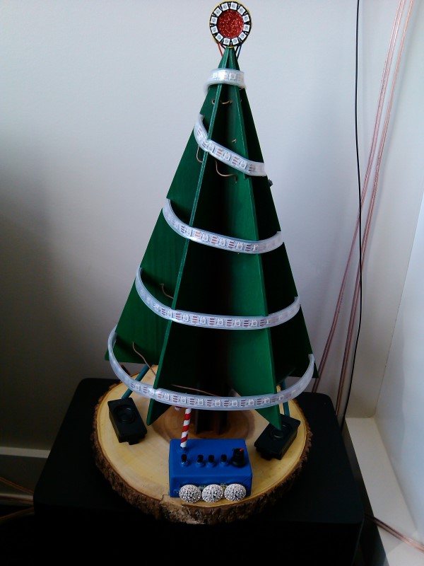
A view of the functionally complete tree follows:
Gift boxes for under the tree were created out of dollar store toys that had a square or rectangular shape, and were then wrapped in Christmas wrapping paper.
A set of ornaments were created using combinations of small beads found at a craft store.
Christmas music was supplied by searching on the web for public domain songs. There were a sufficient number of them for a good selection.

