
By Deid Reimer
What we are going to do is flash a light emitting diode on and off. This demonstrates the fundamentals of using the General Purpose Input Output (GPIO) ports.
The Raspberry Pi’s GPIO pins
The GPIO Pins have the following names and functions. There are two naming conventions: Broadcom numbers, and the standard pin location numbers. Most of the pins can be either inputs or outputs. For this demo we will be using one pin and setting it to an output.
| GPIO# | 2nd func | pin# | pin# | 2nd func | GPIO# | |
|---|---|---|---|---|---|---|
| – | +3V3 | 1 | 2 | +5V | – | |
| GPIO2 | SDA1 (I2C) | 3 | 4 | +5V | – | |
| GPIO3 | SCL1 (I2C) | 5 | 6 | GND | – | |
| GPIO4 | GCLK | 7 | 8 | TXD0 (UART) | GPIO14 | |
| – | GND | 9 | 10 | RXD0 (UART) | GPIO15 | |
| GPIO17 | GEN0 | 11 | 12 | GEN1 | GPIO18 | |
| GPIO27 | GEN2 | 13 | 14 | GND | – | |
| GPIO22 | GEN3 | 15 | 16 | GEN4 | GPIO23 | |
| – | +3V3 | 17 | 18 | GEN5 | GPIO24 | |
| GPIO10 | MOSI (SPI) | 19 | 20 | GND | – | |
| GPIO9 | MISO (SPI) | 21 | 22 | GEN6 | GPIO25 | |
| GPIO11 | SCLK (SPI) | 23 | 24 | CE0_N (SPI) | GPIO8 | |
| – | GND | 25 | 26 | CE1_N (SPI) | GPIO7 | |
| (Models A and B stop here) | ||||||
| EEPROM | ID_SD | 27 | 28 | ID_SC | EEPROM | |
| GPIO5 | – | 29 | 30 | GND | – | |
| GPIO6 | – | 31 | 32 | – | GPIO12 | |
| GPIO13 | – | 33 | 34 | GND | – | |
| GPIO19 | – | 35 | 36 | – | GPIO16 | |
| GPIO26 | – | 37 | 38 | – | GPIO20 | |
| – | GND | 39 | 40 | – | GPIO21 | |
We also need to know something about how much current a Pi pin can supply and how much current it takes to run a LED.
- Amps (Ampères) is the amount of current flowing in an electrical wire or device. See Wikipedia/Ampère
- A typical electrical circuit in your home can provide 15 Amps; over that and the circuit-breaker will trip.
- The typical power supply with your Pi provides a maximum of 2.5 Amps.
- The total current used from all pins on the Pi GPIO should not exceed 50mA (milliAmps or .050 Amps). Each pin should not exceed 16mA.
- Amps = amount of electrical flow
- Volts = electrical pressure
- Resistance = resistance to electrical flow.
To calculate the amount of current we need to know about the resistance of the led and the voltage supplied by the GPIO output.
Resistance of a LED = none. Oops! Diodes are interesting. In one direction they have infinite resistance, no current will flow and in the other they have a fixed voltage drop and then zero resistance. Voltage drop of the blue lead I am using is about 2.6 Volts. (I measured it.)
To calculate current we use Ohms law which is I=E/R. In our example this is (3.3 -2.6)/0, since leds have no resistance after the fixed voltage drop. (See why the Oops!) An infinite amount of current, which means we will probably toast the PI.
We solve this problem by adding resistance. A restriction in the current flow created uniquely enough by a device called a resistor.

So lets calculate the size of the resistor we want:
I=E/R or R = E/I
Max current per pin = 16 ma(3.3-2.6)/.005 = 0.7/.005 = 140 ohms
I think I actually have an approximately 470 ohm resistor in this circuit since I don’t care about brightness.
A little more about leds

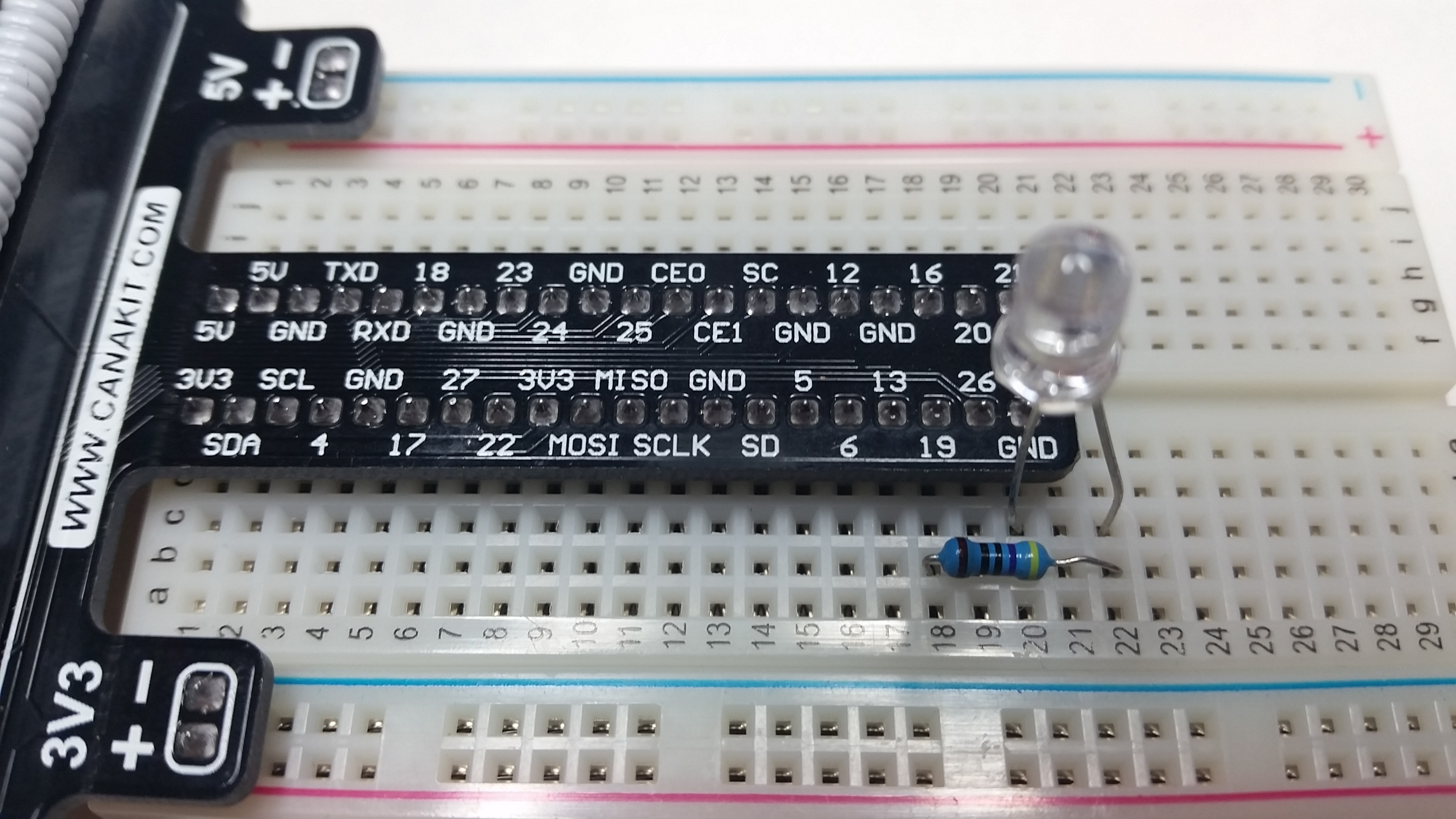
As you can see from the above diagram leds have polarity. They must be inserted in the circuit in the correct direction.
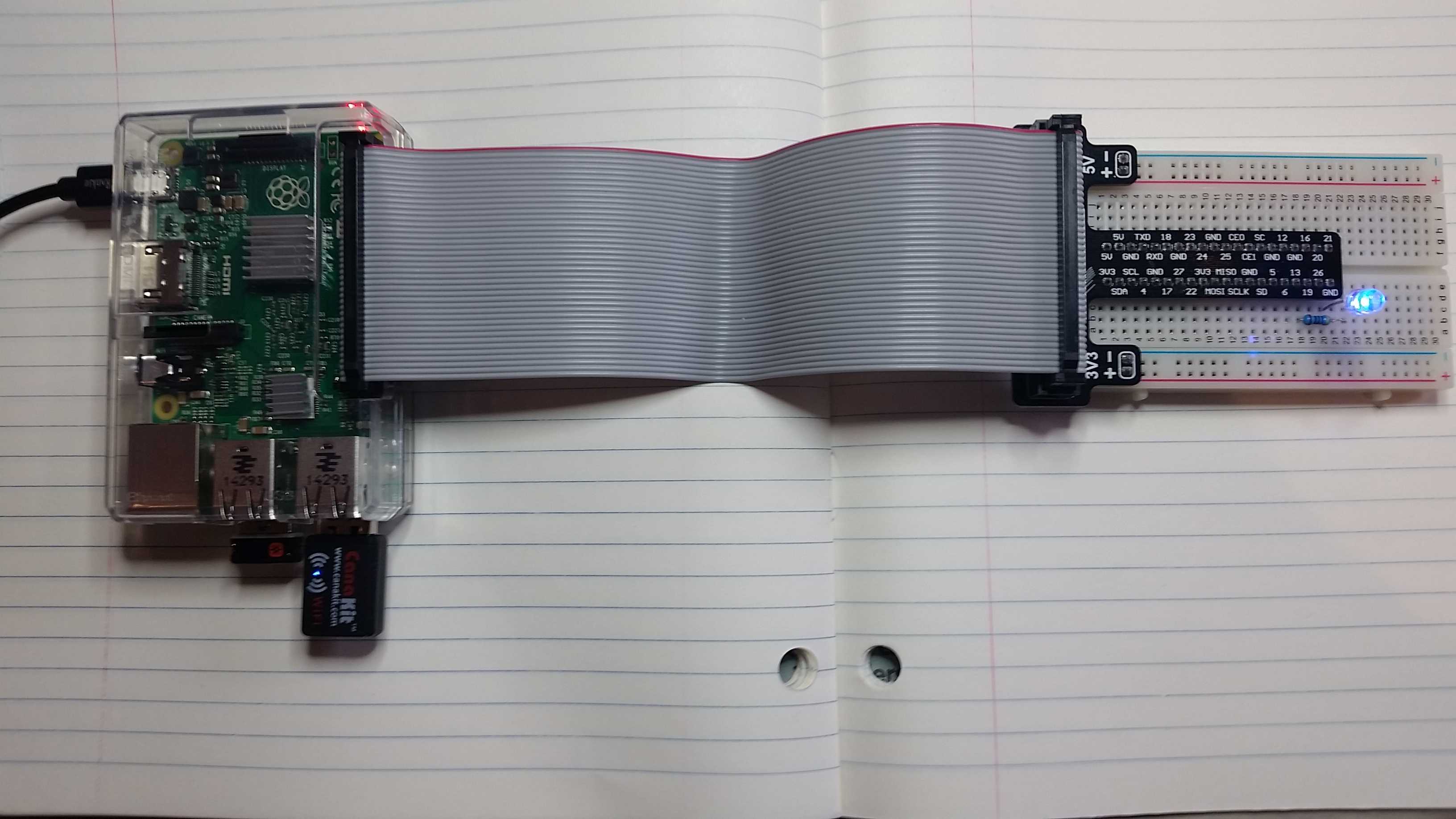
The end result the circuit looks like this:
Or as what we call a schematic diagram:

Note that although this schematic shows that we are connected to pin 16 we are actually using pin 19 in this circuit.
To Review
- The Pi can only supply so much current
- Leds without a resistor will allow an infinite amount of current
- So we add a resistor calculated to limit the current to a reasonable amount
- Leds only work in one direction in a ciruit.
Python Programs
Turn the led on
#! /usr/bin/python

# Import the Python gpio library
import RPi.GPIO as GPIO

# Turn off warnings
GPIO.setwarnings(False)

# This is the gpio pin I have the led connected to
pin = 19

#  Set the pin number mode to Broadcom rather than connector order
GPIO.setmode(GPIO.BCM)

# Set the choosen pin to be an output and set the ouput true, on.
GPIO.setup(pin, GPIO.OUT)
GPIO.output(pin, 1)
Or if we want it to flash a few times:
#! /usr/bin/python

# Flash a LED
import RPi.GPIO as GPIO
import time

GPIO.setwarnings(False)
GPIO.setmode(GPIO.BCM)
pin = 19

GPIO.setup(pin, GPIO.OUT)

# Loop a bunch of times turning the led on and off with a delay of 1 second.
i=0
while i < 20:
GPIO.output(pin, 1)
time.sleep(1)
GPIO.output(pin, 0)
time.sleep(1)
i = i + 1

# Set the gpio pins we used back to the default input state.
GPIO.cleanup()