Secure Android Control of Some Internet Things
Today’s geekiness is a prototype for some homemade, remote
control of ‘things’. A do it yourself Internet of Things
(IoT) infrastructure project.
Almost all products that provide IoT functionality require a
customer to surrender control and privacy to some third
party. The usual form of this surrender is funneling the
thing’s data through the third party’s server. This is
marketed as a typical ‘cloud’ offering and comes with fairly
one-sided terms. I don’t like one-sided deals, so I end up
having to either do without or make my own somehow.
I’ve been mildly interested in home security and automation for a
few years, and I now have the time and resources to dive in and
see what can be done.
Goals
My goals for this project/presentation are:
- Introduce the Beaglebone Black;
- Use a smartphone as a remote control;
- Use the Internet as a conduit for control messages;
- Do this securely – i.e. high resistance to break-in and no
eaves-dropping; - Introduce some useful, but maybe little known technologies.
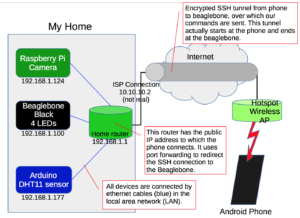
Oh yes, and light an LED and read a sensor. Here is a block
diagram of the infrastructure:
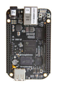
The Beaglebone Black (BBB)
For this project, there are a number of interesting things about
the BBB.
- The board ships with 4GB of on-board flash storage, which has
the Angstrom Linux Distribution installed. The SD card can be
used to hold and boot an entirely different operating system,
without removing the default linux installation. - Ethernet
- 512MB memory
- 2 x 46 pin headers
- USB
- HDMI
- 1 GHz Arm Cortex-A8 processor
- Supports add-ons called capes
I’ll be using the Beaglebone with FreeBSD. To get the best
experience from the beaglebone, we have to use the leading edge
version of FreeBSD, which at the time of this prototype was
12.0-CURRENT. Get
FreeBSD. I downloaded the FreeBSD-12.0-CURRENT-arm-armv6-BEAGLEBONE-20160829-r305028.img
file a few months back, there are more current versions. The
standard method of writing the .img file to an SD card and
inserting the SD card into the BBB applies. A wiki
page of information about FreeBSD on the BBB is a good
reference.
To boot from the SD card, you have to hold down the tiny boot
button (at the same end as the USB port and SD card) while
powering on the device. The FreeBSD image will then
boot. At first boot, it automatically resizes the root
partition to use the entire SD card, which is a bonus. After
that, you login with the default username of root and a
password of root. Change this. There is also a
user named freebsd with a password of freebsd.
Change this as well.
root@beaglebone:~ # passwd
Changing local password for root
New Password:
Retype New Password:
root@beaglebone:~ # passwd freebsd
Changing local password for freebsd
New Password:
Retype New Password:
root@beaglebone:~ #
To find out the system and version, use the uname -a
command:
root@beaglebone:~ # uname -a
FreeBSD beaglebone 12.0-CURRENT FreeBSD 12.0-CURRENT #0 r305028: Tue Aug 30 02:31:26 UTC 2016
root@releng3.nyi.freebsd.org:/usr/obj/arm.armv6/usr/src/sys/BEAGLEBONE arm
A User Account
For secure access to the system, a non-root user account is
required. We’ll create one that will be used with the
smartphone app.
root@beaglebone:~ # adduser
Username: iot
Full name: thingy
Uid (Leave empty for default):
Login group [iot]:
Login group is iot. Invite iot into other groups? []:
Login class [default]:
Shell (sh csh tcsh git-shell nologin) [sh]: tcsh
Home directory [/home/iot]:
Home directory permissions (Leave empty for default):
Use password-based authentication? [yes]:
Use an empty password? (yes/no) [no]:
Use a random password? (yes/no) [no]:
Enter password:
Enter password again:
Lock out the account after creation? [no]:
Username : iot
Password : *****
Full Name : thingy
Uid : 1003
Class :
Groups : iot
Home : /home/iot
Home Mode :
Shell : /bin/tcsh
Locked : no
OK? (yes/no): yes
adduser: INFO: Successfully added (iot) to the user database.
Add another user? (yes/no): no
Goodbye!
The fourth line from the above iot user creation shows
that a group (iot) was also created for the user.
This group will be used for allowing access to the GPIO devices,
as seen in the next section.
Device Filesystem and devfs.conf
On FreeBSD, giving access to devices is done by altering
permissions on the device filesystem–devfs. Devices
can be configured at boot time using some settings in the devfs
configuration file, which is named: /etc/devfs.conf.
To find out which devices we need to access for GPIO, we can
produce a directory listing of the /dev/ directory:
root@beaglebone:~ # ls /dev
bpf fd klog nfslock
bpf0 fido kmem null
console full led openfirm
consolectl geom.ctl log pruss0
ctty gpioc0 mdctl ptmx
cuau0 gpioc1 mem pts
cuau0.init gpioc2 mmcsd0 random
cuau0.lock gpioc3 ...
The obvious candidates are the gpiocN files, where
N is an integer from 0 to 3. These devices are the four GPIO
controller buses. To allow the iot user to control
(read/write) the pins on the beaglebone, we edit the /etc/devfs.conf
file and add the following 8 lines.
# vi /etc/devfs.conf
# ...
own gpioc0 root:iot
perm gpioc0 0660
own gpioc1 root:iot
perm gpioc1 0660
own gpioc2 root:iot
perm gpioc2 0660
own gpioc3 root:iot
perm gpioc3 0660
The ‘own‘ line sets the owner of the device file to the root
user and the group of the device file to the iot
group. The ‘perm‘ line assigns permissions (0660) to
the device file such that the owner and group have read/write
permissions. Therefore, a normal user who is a member of the
iot group would be allowed access to the devices. The
use of the group for control of the device allows us to remove the
very dangerous problem of requiring the root user to run
the programs that interact with the GPIO pins. This
principle of least privilege, i.e. the using of a normal user for
specific tasks, is a best practice for security.
Once the changes are made, we can restart the devfs
system service. The traditional way with an rc.d
script is shown below. A more modern way is to use the
command: service devfs restart.
root@beaglebone:/etc # /etc/rc.d/devfs restart
If we now look at the GPIO controller bus devices, we see that
the group iot has read/write permissions.
root@beaglebone:/etc # ls -la /dev/gp*
crw-rw---- 1 root iot 0x22 Oct 22 00:39 /dev/gpioc0
crw-rw---- 1 root iot 0x27 Oct 22 00:39 /dev/gpioc1
crw-rw---- 1 root iot 0x28 Oct 22 00:39 /dev/gpioc2
crw-rw---- 1 root iot 0x29 Oct 22 00:39 /dev/gpioc3
The Controller Script
The controller.py program is written
in python and is designed to be executed via a secure shell (SSH)
connection. We’ll look a bit closer at how SSH works
below. A C library
and python module was created for GPIO use on FreeBSD by R.
Paulo. I had to download the zip file of the source code
archive, extract the files, and run the python installation
command.
iot@beaglebone:~/dev/gpio % unzip 1dfe793d0b0c.zip
Archive: 1dfe793d0b0c.zip
extracting: rpaulo-libgpio-1dfe793d0b0c/.hg_archival.txt
extracting: rpaulo-libgpio-1dfe793d0b0c/.hgignore
extracting: rpaulo-libgpio-1dfe793d0b0c/CMakeLists.txt
extracting: rpaulo-libgpio-1dfe793d0b0c/gpio.c
extracting: rpaulo-libgpio-1dfe793d0b0c/gpioctl/CMakeLists.txt
extracting: rpaulo-libgpio-1dfe793d0b0c/gpioctl/gpioctl.c
extracting: rpaulo-libgpio-1dfe793d0b0c/libgpio.h
extracting: rpaulo-libgpio-1dfe793d0b0c/python/CMakeLists.txt
extracting: rpaulo-libgpio-1dfe793d0b0c/python/GPIO/GPIO.py
extracting: rpaulo-libgpio-1dfe793d0b0c/python/GPIO/__init__.py
extracting: rpaulo-libgpio-1dfe793d0b0c/python/setup.py
iot@beaglebone:~/dev/gpio % cd rpaulo-libgpio-1dfe793d0b0c/
iot@beaglebone:~/dev/gpio/rpaulo-libgpio-1dfe793d0b0c % ls
CMakeLists.txt gpio.c gpioctl libgpio.h python
iot@beaglebone:~/dev/gpio/rpaulo-libgpio-1dfe793d0b0c % cd python
iot@beaglebone:~/dev/gpio/rpaulo-libgpio-1dfe793d0b0c/python % ls
CMakeLists.txt GPIO __init__.py setup.py
As the root user, install the python module.
root@beaglebone:~ # cd ~iot/dev/gpio/rpaulo-libgpio-1dfe793d0b0c/python
root@beaglebone:~iot/dev/gpio/rpaulo-libgpio-1dfe793d0b0c/python # python setup.py install
python: Command not found.
root@beaglebone:~iot/dev/gpio/rpaulo-libgpio-1dfe793d0b0c/python # python2 setup.py install
running install
running build
running build_py
creating build
creating build/lib
creating build/lib/GPIO
copying GPIO/GPIO.py -> build/lib/GPIO
copying GPIO/__init__.py -> build/lib/GPIO
running install_lib
running install_egg_info
Removing /usr/local/lib/python2.7/site-packages/GPIO-0.1-py2.7.egg-info
Writing /usr/local/lib/python2.7/site-packages/GPIO-0.1-py2.7.egg-info
That’s the preliminary setup for the beaglebone. We still
have to setup the SSH portion and the controller script.
The Smartphone
I decided to use the Android development platform for the very
simple reason that I have an Android phone. I usually carry
it with me and I have a small data plan for use in testing.
I could have chosen iOS since I have an iPad, but I don’t carry my
iPad anywhere and since I don’t have an iPhone, I wouldn’t have
much success with remote control without a remote.
Google provides Android development kit, known as Android
Studio freely to anyone who wants to download it. It can
be fiendishly complex, but getting started is straightforward and I
highly recommend the tutorials that can be found on YouTube.
The Developer’s
Guide has many excellent examples that can be freely copied
and used as a basis for your own code. I usually read a
section while grinding along on the YMCA’s Internet connected
elliptical exercise machines.
A fairly important consideration is whether or not I have the
freedom to write programs for the device. In the Android
case, I can use the studio software on almost any computer
operating system. There are Windows, MacOS and even Linux
versions available. I am currently trying to get it working
on FreeBSD. To write software for an iPhone or iPad, I
would have to use a MacOS system exclusively with its Xcode
development platform. I could do this, since I have a
Macbook Pro with Xcode installed and I have experience writing iOS
apps. It seems better though, to use a development platform
that is open to a wider audience. A further minor concern is
access to the app stores. It’s minor because I can write and
place my apps directly on my own devices without having to go
through any stores. This is sometimes referred to as
side-loading. Last I checked, Google requires a one time fee
of US$25 and a google account, while Apple requires an annual fee
of US$99 and an Apple ID. Both have account verification
processes and the requirement to provide personal
information. Both take a 30% cut of your top line
revenue. There are other android app stores (Amazon, for
instance), but no other iOS app stores. An article
written by Tim Mackenzie gives a good summary.
For the do-it-yourself option, android makes the most sense,
since phones can be either expensive or cheap (iPhones are
strictly expensive). If you decide to distribute your app,
android is less expensive with the one time fee, plus you could
try more than one app store. If you don’t care about selling
your app, you can give it to anyone as a single packaged file
(hosted on your own website) and allow people to install it on
their own phone. This can’t be done using iOS without
resorting to what is called jailbreaking an iPhone.
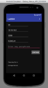
The LED SSH app
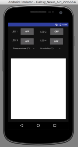
The blank space on the right hand operational screen would
normally show the camera scene from the raspberry pi.
Unfortunately, I haven’t figured out why the emulator won’t
display this content, when a real phone will. It is likely
an issue with the SSH port forwarding not being supported in the
emulator somehow (perhaps a localhost issue).
A zip file of the Android project is available: LEDSSH.zip, this file
only contains the files under the src/ directory’s main/ directory
and is not a complete copy of the project. The code included
is certainly enough for you to copy it and use it in your own app.
The main screen’s source code is here: MainActivitySSH.java
The operational screen’s source code is here: OperateLEDs.java
The Internet
There are several components that are required for a remote
control to work over the Internet.
- You need to know your Internet address;
- You need to allow control signals to reach into your home
network and talk to your things; - You need to tell your things to do something.
Internet Address
In order for this infrastructure to work, you’ll need to know and
store the IP address of your home internet connection. In
many cases, Canadian ISPs give you a dynamic IP address, which
usually means that it can change without warning. However,
the nature of this dynamic assignment (dynamic host configuration
protocol (DHCP)) is such that the address given is leased for a
period of time. This lease is renewed at regular intervals
and the address assignment rarely changes. I have had the IP
address assigned to my home only change once in the 1.5 years I’ve
had my service. This is typical. Prolonged power
outages may cause your IP to change as can internal network
reorganization at the ISP.
If you own a domain and have a DNS service setup, you can setup a
hostname that points to your home ISP connection. Another
alternative is to use a service that provides monitoring of your
IP address and gives it a host name. It’s beyond the scope
of this presentation as to what services currently exist.
In this project, my home address is 10.10.10.2, which is not my
real address, but is useful as an example for the simulation of
the Internet we’re doing here. The Trendnet (blue) router
that I brought acts as the phone’s Internet service–imagine it is
the WiFi hotspot or cellular data connection provider. The
Netgear (black) router acts as my home Internet connection.
Port Forwarding
Most home routers do not allow an incoming connection to get
through to the internal network. This is usually due to the
router’s common behaviour of using network address translation
(NAT), which takes internal traffic and converts it for use on the
public Internet. The end result of this process is that if
an incoming connection does not map to an already established
outgoing connection, the incoming data packet is ignored.
The standard method of overcoming this NAT property and traversing
a NAT router is to setup port forwarding for incoming
connections.
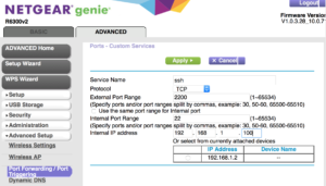
If we want to connect to TCP (transmission control protocol) port
22 (the SSH default, like port 80 is the HTTP/web default) on the
beaglebone at IP address 192.168.1.100, then we have to setup port
forwarding on the Netgear router. Since 22 is a common port
for bad people to attack, we can minimize the annoyance factor by
specifying a non-standard number for forwarding. Here, we’ll
use 2200, which has 22 in it so it reminds us of SSH.
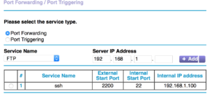
The completed port forwarding setup is shown in the image below,
we see the target port, the redirected port and the internal IP
address.
The bottom line is that any connections to 10.10.10.2:2200 will
now get sent to 192.168.1.100:22 for action. The phone will
use 10.10.10.2:2200 and won’t need to know anything about where
the SSH service is really listening internally.
Thing Control
Today’s market for home automation includes many solutions, but
the majority of them require you to run your connection through
third party servers. This is usually to provide you with
convenience (it’s hard to do-it-yourself, right?). Some
problems with this are:
- You have no idea how long the business will provide the
server. If they stop, you’ll have no way to use your home
automation system. - The business can gather information about how and when you use
the system, and then sell this information. - A criminal hacker can break in to the service company and
steal customer information and possibly use this to break into
your home systems. - The company may charge a monthly subscription fee for the
service (can be acceptable, depends).
Security
A good way to make sure that a connection to your thing
controller is secure is to use the Secure SHell (SSH) software
suite. This software allows for an amazing amount of useful
functionality. Some examples are:
- Encrypted connections to prevent eves-dropping or control
tampering; - Two factor authentication (something you have and something
you know); - Strict end point control of programs that are executed.
Some important configuration switches for an SSH server are
contained in its configuration file, usually found at
/etc/ssh/sshd_config.
iot@beaglebone:~ % cat /etc/ssh/sshd_config | grep -v ^#
# All the rest of the config. items are left to their default
# and in the comments within the file.

LogLevel DEBUG

PermitRootLogin no

PubkeyAuthentication yes

AuthorizedKeysFile .ssh/authorized_keys .ssh/authorized_keys2

PasswordAuthentication yes
ChallengeResponseAuthentication no
UseDNS no

Subsystem sftp /usr/libexec/sftp-server

Match User iot
PasswordAuthentication no
The above combination of settings stops the iot user from
logging in via password, but allows other users to do so. root
is never allowed to login over SSH, only unprivileged users can
login and then they must become root using the su –
command. This is a security best practice.
Encryption
An SSH connection always uses encryption, regardless of the
method used to initiate the connection (key pairs, or a simple
password). No one can eaves-drop on this connection nor can
they alter the data within the connection. In security terms
this is known as confidentiality and integrity.
Two Factors–Public/Private Key Pairs and a Passphrase
The method we use for our SSH control connection uses asymmetric
encryption which uses key pairs. There is a public key,
which lives on the SSH server and a matching private key, which
lives on the phone. These two keys are intertwined by some
really complex math that guarantees that if something is scrambled
(i.e. encrypted) with the private key, only the public key can
descramble (i.e. decrypt) it, and vice-versa. These keys are
the first part of the two-factors, that is, something we
have. The second factor is a passphrase (something we know),
which we use to protect the private key that lives on your
phone. It is recommended practice to passphrase protect
private keys. This two-factor method is effective because if
someone steals your phone, they’ll have the private key, but won’t
necessarily have the passphrase, or if someone finds out your
passphrase (by looking over your shoulder), they won’t have the
private key and the passphrase won’t be useful. Always use a
unique passphrase for different keys and services and don’t reuse
passwords for important services.
Generating a public/private key pair is easy. It can be
done on the beaglebone or raspberry pi using a program called ssh-keygen.
mv@beaglebone:~ % ssh-keygen -b 2048 -t rsa -C "IoT Key" -f controller_key
Generating public/private rsa key pair.
Enter passphrase (empty for no passphrase):
Enter same passphrase again:
Your identification has been saved in controller_key.
Your public key has been saved in controller_key.pub.
The key fingerprint is:
SHA256:5TDQUAeTuwYVrMSZBZSl69Lk16cmubdR/O/y8S2AX00 IoT Key
The key's randomart image is:
+---[RSA 2048]----+
| o=%B+. |
| *o=o |
| ..oo.. |
| o..= . E|
| o.S...o o |
| = o...... .|
| . +...o..o.. |
| . .o o+. o.+|
| .=o. =*|
+----[SHA256]-----+

mv@beaglebone:~ % ls -la *key*
-rw------- 1 mv mv 1766 Jan 12 21:19 controller_key
-rw-r--r-- 1 mv mv 389 Jan 12 21:19 controller_key.pub
mv@beaglebone:~ % more controller_key.pub
ssh-rsa AAAAB3NzaC1yc2EAAAADAQAB...HRWti/AtJ5WRueouvDrJkmu
Tip99BGG1Ma8FmJlcaE8N8iItWTpVu+PvuHz4XVITuzK7l4x.. IoT Key
The public part of this key pair has the .pub
extension. It has a special purpose and is placed in a file
called authorized_keys on the SSH server system. The
location of the authorized_keys file is dependent on the
user account that we created to act as the intermediary for our
control signals. This was the iot account. The
actual file location on the beaglebone is then: /home/iot/.ssh/authorized_keys
iot@beaglebone:~ % more .ssh/authorized_keys
command="/home/iot/dev/gpio/controller.py",no-X11-forwarding,no-pty,no-user-rc,no-agent-forwarding
ssh-rsa AAAAB3NzaC1yc2EAAAADAQABAAABAQC8VVa0jH6NkvOqE4Rqk5...j2RN6YtYtlFj3wilqCJ4w IoT Key
Make sure that the entry above is just one single (long)
line. Note that the key has been truncated and there is a
single space between no-agent-forwarding and ssh-rsa.
Execution of the Controller Script Only
The usual way to use public key authentication is to place the
public key in the authorized_keys file and specify the
private key as an identity when connecting. This connection
usually results in a command line shell allowing for general
purpose or arbitrary commands to be executed by the user (iot).
We don’t want this, since if the key and passphrase are
compromised, we want to limit what an attacker can do.
Fortunately, SSH allows us to restrict what program is run when
using a particular key pair.
If we place the following options in front of the public key
within the authorized_keys file we restrict dramatically
what the iot user can do on our server.
command="/home/iot/dev/gpio/controller.py",no-X11-forwarding,no-pty,no-user-rc,no-agent-forwarding
Make sure there are no spaces between the options. Each
option means:
- command=”/home/iot/dev/gpio/controller.py” – run only this
command, nothing else; - no-X11-forwarding – do not allow X programs to be run over
this connection; - no-pty – do not allocate a terminal to this connection;
- no-user-rc – do not execute any commands in a file called ~/.ssh/rc;
- no-agent-forwarding – do not allow any forwarding of SSH agent
credentials.
One restrictive option that is normally included is no-port-forwarding,
but we will be using port-forwarding with our connection.
This is NOT the same port forwarding described above. The
raspberry pi section will describe how we use SSH port forwarding,
within the SSH tunnel, to connect to the camera’s HTTP output
stream.
The Things
We’ll use a hub and spoke method for our thing control. For
this prototype, the hub will be the FreeBSD system on the
Beaglebone Black (BBB) microprocessor. The spokes will be a
set of LEDs on the BBB, a single arduino with ethernet shield that
returns temperature and humidity, and a Raspberry Pi 3 with a
camera.
Arduino
The arduino has a DHT11 temperature and humidity sensor attached
to it. It uses an ethernet shield for networking and acts as
a web server. The only page served by the web server is a
plain text document with the temperature number, followed by a
space and then the humidity number.
This web server has an IP address of 192.168.1.177 and listens on
port 80. Our controller script asks the web server for the
temperature and humidity each time it is run, and returns this
information with the LED status.
Here is the source code for the arduino server: iotserver.ino
.
/*
  Web Server

 A simple web server that shows the value of the
 DHT11 temperature and humidity sensor.
 Uses an Arduino Wiznet 5100 Ethernet shield.

 Circuit:
 * Ethernet shield attached to pins 10, 11, 12, 13
 * DHT11 attached to digital pin 8.

 created 18 Dec 2009
 by David A. Mellis
 modified 9 Apr 2012
 by Tom Igoe
 modified 02 Sept 2015
 by Arturo Guadalupi
 modified 07 Jan 2017
 by Mark Giovannetti

 */

#include <SPI.h>
#include <Ethernet.h>
#include <dht11.h>

DHT11 DHT11;  // Declare our sensor object

#define DHT11PIN 8  // DHT11 attach to digital pin 8 on controller board

// Enter a MAC address and IP address for your controller below.
// The IP address will be dependent on your local network:
byte mac[] = {
 0xDE, 0xAD, 0xBE, 0xEF, 0xFE, 0xED
};
IPAddress ip(192, 168, 1, 177);

// Initialize the Ethernet server library
// with the IP address and port you want to use
// (port 80 is default for HTTP):
EthernetServer server(80);

int temperature = -999;  // Default values to act as sentinels
int humidity = -999;     // -999  means no data available

void setup() {
 // Open serial communications and wait for port to open:
 Serial.begin(9600);
 while (!Serial) {
   ; // wait for serial port to connect. Needed for native USB port only
 }

 // start the Ethernet connection and the server:
 Ethernet.begin(mac, ip);
 server.begin();
 Serial.print("server is at ");
 Serial.println(Ethernet.localIP());
}


void loop() {

 // listen for incoming clients
 EthernetClient client = server.available();

 if (client) {
   Serial.println("new client");

   // read the value returned from sensor
   Serial.print("Checking DHT11,\t");
   int chk = DHT11.read(DHT11PIN);
   switch (chk)
   {
     case DHTLIB_OK:
     Serial.print("OK \t");
     temperature = DHT11.temperature;
     humidity = DHT11.humidity;
     break;
     case DHTLIB_ERROR_CHECKSUM:
     Serial.print("Checksum error,\t");
     temperature = -999;
     humidity = 0;
     break;
     case DHTLIB_ERROR_TIMEOUT:
     temperature = 0;
     humidity = -999;
     Serial.print("Time out error,\t");
     break;
     default:
     temperature = -999;
     humidity = -999;
     Serial.print("Unknown error,\t");
     break;
   }
   Serial.println();
   // Display values to serial log
   Serial.print("Tem: ");
   Serial.print(DHT11.temperature); //print the temperature on serial monitor
   Serial.println(" C");
   Serial.print("Hum: ");
   Serial.print(DHT11.humidity); //print the humidity on serial monitor
   Serial.println(" %");
   Serial.println();

   // an http request ends with a blank line
   boolean currentLineIsBlank = true;
   while (client.connected()) {
     if (client.available()) {
       char c = client.read();
       Serial.write(c);
       // if you've gotten to the end of the line (received a newline
       // character) and the line is blank, the http request has ended,
       // so you can send a reply
       if (c == '\n' && currentLineIsBlank) {
         // send a standard http response header
         client.println("HTTP/1.1 200 OK");
         client.println("Content-Type: text/plain");
         client.println("Connection: close");  // the connection will be closed after completion of the response
         client.println();
         client.print(temperature);
         client.print(" ");
         client.print(humidity);
         break;
       }
       if (c == '\n') {
         // you're starting a new line
         currentLineIsBlank = true;
       } else if (c != '\r') {
         // you've gotten a character on the current line
         currentLineIsBlank = false;
       }
     }
   }
   // give the web browser time to receive the data
   delay(5);
   // close the connection:
   client.stop();
   Serial.println("client disconnected");
 }
}
Raspberry Pi 3
The raspberry pi has an excellent camera facility that we use to
verify whether our LEDs are doing what they’re told. Of
course, we can use the camera in a more useful manner, such as
looking out the front door, or watching whether the neighbour’s
dog is abusing your lawn. The version
2 camera has been covered in other presentations, so I won’t
go into too much detail.
We want to just stream live images as fast as possible, and with
a minimum of latency. This can be achieved (after much web
searching) using the built-in raspistill command and the mjpg_streamer
software.
The next bit of code is a shell script that is simplicity itself
and does all the heavy lifting for serving the camera’s live image
stream. I found it on the web, but can’t recall where.
pi@raspberrypi:~ $ more run_streamer.sh

#!/bin/sh

mkdir /tmp/stream

raspistill --nopreview -w 480 -h 360 -q 5 -o \
/tmp/stream/pic.jpg -tl 100 -t 0 -th 0:0:0 &

LD_LIBRARY_PATH=/usr/local/lib mjpg_streamer -i \
"input_file.so -f /tmp/stream -n pic.jpg" -o \
"output_http.so -w /usr/local/www"
The first line tells the command shell that this file contains a
/bin/sh script. The next line creates a temporary
directory for the stream images. The raspistill line starts
a process that runs continously and takes a snapshot every 100
milliseconds, and places the image (pic.jpg) in the /tmp/stream
directory.
The last command starts the mjpg_streamer software which
watches the /tmp/stream directory for changes to the pic.jpg
file and performs some streaming magic. This software acts
as an HTTP server on port 8080. To view the stream, we use
the URL http://192.168.1.124:8080/?action=stream. This URL
is called indirectly on the smartphone via SSH port
forwarding.
SSH Port Forwarding
Our smartphone has a section of code that creates an SSH
connection to the server that is designed to persist while the app
is running. This is different than the LED control
connections which simply connect, issue a command, get the
response, and then disconnect. Viewing a live camera stream
requires a continuous connection, and we setup this connection as
a “video tunnel”. Looking at the controller.py code
below shows the VIDEO command simply exiting. This
connection is terminated easily by the smartphone, when the app is
closed.
In our phone code, we tell the SSH connection that we want to use
local port forwarding so that when we connect to a local port on
the phone, the connection is picked up by SSH and forwarded
through the tunnel and sent to the target of the port forwarding
command.
Beaglebone Black
Most of the BBB’s configuration was discussed earlier.
Now let’s have a look at the controller.py script:
#!/usr/bin/env python2
#
import time
import os
from GPIO import GPIO as GP
import urllib2

"""
This script is run via an SSH forced command that is tied to a
particular user and public/private key pair.

Commands are read using the original ssh command and are therefore
available to this script via the SSH_ORIGINAL_COMMAND environment
variable.

A set of valid commands are whitelisted and the passed command is
checked against this list using an if-formatted case pattern.
All commands result in a return of the new state of all LEDs (an
implied new status command).

LEDs are numbered 1, 2, 3, and 4 on the android app's user interface,
so as to be user friendly.  Don't confuse the 0 based array index in
ledState with the LED number.

LED numbers are passed as an argument to the command.  There is
a space separating the command from its LED arguments.  The
LED argument is a comma delimited list of one or more numbers
representing the LEDs to operate on.  Examples:

3
2,4
1,2,3,4

The ALL argument can be used to have the command operate on
all LEDs.  It is a short cut way of specifying 1,2,3,4.

Commands are:

STATUS
- return a pattern indicating LED state (on/off)
- also returns a temperature and humidity from a networked
  arduino sensor.

The returned string is a JSON formatted array indicating
the state of each LED, 0 (LOW) respresenting OFF and 1 (HIGH) representing ON.
The array's first element represents the first LED which is usually
pin 21 on the beaglebone black (BBB).  The remaining elements are
the rest of the pins 22, 23, and 24 in order (i.e. LED numbers 1
through 4).

A sample returned string is as follows (JSON array):

 [0, 1, 0, 0, 20, 25]
Above, the LED on pin 22 (LED 2) is lit up, while the other three LEDs are
off.  The temperature is 20C and the humidity is 25%.


OFF ALL
- set all LEDs to off.

ON ALL
- set all LEDs to on.

OFF n1[,n2,...]
- set numbered LEDs to off.

ON n1[,n2,...]
- set numbered LEDs to on.

"""

# The controller that has the 4 user LEDs is given the number 1 as in
# /dev/gpioc1

GPIO_CONTROLLER = 1
LOW = 0
HIGH = 1

leftBracket = "["
rightBracket = "]"

temperature = -999
humidity = -999

def JSONstate(leftDelimiter = "[", state_array = [], rightDelimiter = "]"):
 state_string = ", ".join([str(i) for i in state_array])
 return "".join([leftDelimiter, state_string, rightDelimiter])

def getSensorData():
   global temperature, humidity
   try:
       response = urllib2.urlopen('http://192.168.1.177/', timeout=1)
       html = response.read()
       temperature, humidity = html.split(" ")
   except urllib2.URLError, e:
       pass

pinBus = GP.GPIO(GPIO_CONTROLLER)
numPins = 4
ledPins = [21, 22, 23, 24]
ledNums = [1, 2, 3, 4]
ledState = [0, 0, 0, 0]

# Get the current state of the LEDs
for index, pin in enumerate(ledPins):
 ledState[index] = pinBus.pin_get(pin)

def get_pins_from_command(command):
 """
 Take the string command, split it on a single space, and then
 try and parse the LED number arguments.  Returns an empty list
 when things go wrong.  Ignores non numeric LED numbers.
 The LED num argument is a comma separated list of LED numbers
 between 1 and 4 inclusive.
 """
 command_parts = command.split(" ")
 if(len(command_parts) != 2):
   print("Command parts not equal to 2: ", command)
   return []  # bad arguments, bail, should complain TODO log

 else:
   possible_led_numbers = command_parts[1].split(",")
   num_led_args = len(possible_led_numbers)
   if (num_led_args <=0 or num_led_args > 4):
     print("Count of possible led numbers out of range: ", num_led_args)
     return []  # bad arguments, bail, should complain TODO log

   good_led_numbers = []

   for n in possible_led_numbers:
     try:
       num = int(n.strip())
     except ValueError:
       print("Value error on conversion of: ", n)
       continue
     if (num in ledNums):
       good_led_numbers.append(ledPins[num-1])

   return good_led_numbers

commandText = os.environ.get("SSH_ORIGINAL_COMMAND", "NONE")
#commandText = "STATUS"
#commandText = "OFF ALL"
#commandText = "ON ALL"
#commandText = "ON 1,4"

if (commandText == "STATUS" ):
 pass

elif (commandText == "ON ALL"):
 for index, pin in enumerate(ledPins):
   if (ledState[index] == LOW):
     pinBus.pin_set(pin, HIGH)

elif (commandText == "OFF ALL"):
 for index, pin in enumerate(ledPins):
   if (ledState[index] == HIGH):
     pinBus.pin_set(pin, LOW)

elif (commandText.startswith("ON ")):
 pin_args = get_pins_from_command(commandText)  # returns a list of pin numbers (21, ...)
 for index, pin in enumerate(pin_args):
   pinBus.pin_set(pin, HIGH)

elif (commandText.startswith("OFF ")):
 pin_args = get_pins_from_command(commandText)  # returns a list of pin numbers (21, ...)
 for index, pin in enumerate(pin_args):
   pinBus.pin_set(pin, LOW)

elif (commandText.startswith("VIDEO ")):
 print("Running video")
 exit()

else:
 pass # unknown command, this is a good item to log for security purposes TODO

getSensorData()

# Get the updated state of the LEDs
for index, pin in enumerate(ledPins):
 ledState[index] = pinBus.pin_get(pin)
ledState.append(temperature)
ledState.append(humidity)

# return the JSON status array to the android caller
print(JSONstate(leftBracket, ledState, rightBracket))
Conclusion
That concludes this presentation. This shows just one way
to get started creating a do-it-yourself
home automation system. There may be many other methods
using different protocols and of course, you
may want to create an iOS app if you have an iPhone. That
task is left as an exercise for the student.

