by Eileen A.
(with a little help from Cody)
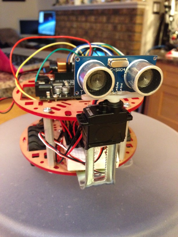
Last March Break, I read a book that changed my life. I ran out and got an Arduino immediately and the Raspberry Pi was not far behind. After a few months of experimenting, and watching YouTube videos of kids building Obstacle Avoidance Robots (OAR), we thought it looked like a good first project. We call it Bobby OAR. An OAR is an autonomous robot that rolls around and avoids obstacles by using sensor input. Then, based on programming, finds an alternate path forward, avoiding obstacles along the way. We had most of the components from various kits, so only a chassis and wheels needed to be ordered. Or was there something else?
Parts

- Parts Arduino clone (Queale)
- Ultrasonic sensor
- Servo motor
- jumper cables
- h-bridge
- dc battery pack & batteries
- 9V battery clip & battery
- mini breadboard
- chassis (BCRobotics)
- wheels
- dc motors with brackets and hardware
- various stand-offs*
- nuts and bolts*
- furniture repair hardware* (Canadian Tire)
- swivel wheel
- closet bracket
- hot glue
- double sided tape and electrical tape
The assembly of the chassis was mostly done by trial and error and required some imagination, digging through our small parts containers in the garage, shopping at Canadian Tire and finally breaking out the Dremel tool. As this was our first project we did have to get a few basic supplies.*
The robot has three main subsystems: the wheels run by two dc motors, the ultrasonic sensor and the servo motor.
1. DC Motors:
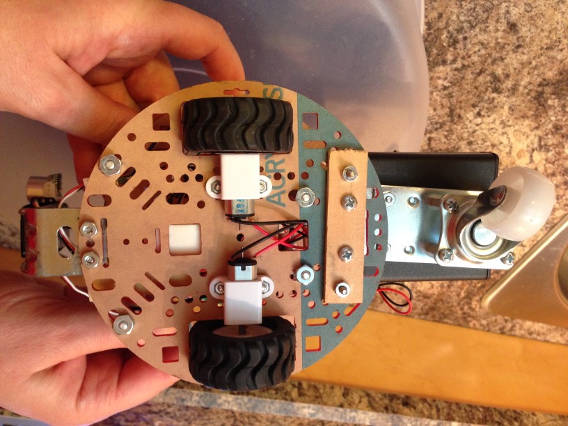
The dc motors and wheels were attached to the bottom part of the chassis and needed to be connected via an h-bridge to the Arduino. The following video provides a good explanation of what each pin on the h-bridge does. It also explains how to connect the h-bridge to the Arduino and to a separate power supply.
https://www.youtube.com/watch?v=5nDaHJqruq0 (Arduino Tutorial #7, 18:33 min)
The following schematic shows how to connect one motor to one side of the h-bridge. The other side of the h-bridge is wired in the same way, in order to run the second motor.
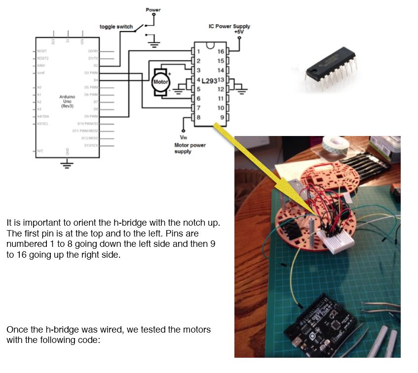
/* DC Motor Test: The following code will make the robot move forward for 4 sec, stop for 1 sec, turn left for 0.4 sec, stop for 1 sec, turn right for 0.4 sec, stop for one sec, go backward for 2 sec, stop for 1 sec, and repeat. */

const int MotorR1 = 6; //forward right motor
const int MotorR2 = 7; // backward right motor

const int MotorL1 = 4; // forward left motor
const int MotorL2 = 5; // backward left motor
void setup() {
  pinMode(MotorR1, OUTPUT);
  pinMode(MotorR2, OUTPUT);
  pinMode(MotorL1, OUTPUT);
  pinMode(MotorL2, OUTPUT);

  digitalWrite(MotorR1, LOW);
  digitalWrite(MotorR2, LOW);
  digitalWrite(MotorL1, LOW);
  digitalWrite(MotorL2, LOW);
}

void loop() {
  //go forward
  digitalWrite(MotorR1, HIGH);
  digitalWrite(MotorR2, LOW);
  digitalWrite(MotorL1, HIGH);
  digitalWrite(MotorL2, LOW);
  delay(4000);

 //stop
  digitalWrite(MotorR1, LOW);
  digitalWrite(MotorR2, LOW);
  digitalWrite(MotorL1, LOW);
  digitalWrite(MotorL2, LOW);
  delay(1000);

 //turn left
  digitalWrite(MotorR1, HIGH);
  digitalWrite(MotorR2, LOW);
  digitalWrite(MotorL1, LOW);
  digitalWrite(MotorL2, HIGH);
  delay(400);

 //stop
  digitalWrite(MotorR1, LOW);
  digitalWrite(MotorR2, LOW);
  digitalWrite(MotorL1, LOW);
  digitalWrite(MotorL2, LOW);
  delay(1000);
 //turn right
  digitalWrite(MotorR1, LOW);
  digitalWrite(MotorR2, HIGH);
  digitalWrite(MotorL1, HIGH);
  digitalWrite(MotorL2, LOW);
  delay(400);

 //stop
  digitalWrite(MotorR1, LOW);
  digitalWrite(MotorR2, LOW);
  digitalWrite(MotorL1, LOW);
  digitalWrite(MotorL2, LOW);
  delay(1000);

 //go backwards
  digitalWrite(MotorR1, LOW);
  digitalWrite(MotorR2, HIGH);
  digitalWrite(MotorL1, LOW);
  digitalWrite(MotorL2, HIGH);
  delay(2000);

 //stop
  digitalWrite(MotorR1, LOW);
  digitalWrite(MotorR2, LOW);
  digitalWrite(MotorL1, LOW);
  digitalWrite(MotorL2, LOW);
 delay(1000);
}
2. Ultrasonic Sensor (Ping)
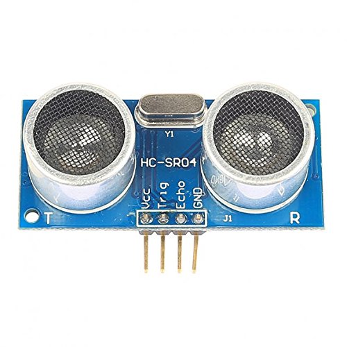 Once the motors were working, it was time to add the second sub-system to our robot. The ultrasonic sensor is used to detect obstacles in the robots path. It does this by creating a sound pulse of 40 kHz and then listens to hear the echo. If an echo is detected the travel time of the sound wave in air is divided by 2 and converted into centimetres. The value returned can then be viewed on the serial monitor or sent to the Arduino.
This editor disallows angle brackets in the html tag pre. Don’t forget your ping library… #include
// ----------------------------------------------------
// Example NewPing library sketch that does a ping about 20 times per second.
// ----------------------------------------------------

#include NewPing.h  // Angle brackets required.
#define TRIGGER_PIN  12  // Arduino pin tied to trigger pin on the ultrasonic sensor.
#define ECHO_PIN     11  // Arduino pin tied to echo pin on the ultrasonic sensor.
#define MAX_DISTANCE 200 // Maximum distance we want to ping for (in centimeters). Maximum sensor distance is rated at 400-500cm.

NewPing sonar(TRIGGER_PIN, ECHO_PIN, MAX_DISTANCE); // NewPing setup of pins and maximum distance.

void setup() {
  Serial.begin(9600); // Open serial monitor at 115200 baud to see ping results.
}

void loop() {
delay(50);           // Wait 50ms between pings (about 20 pings/sec). 29ms should be the shortest delay between pings.
Serial.print("Ping: ");
Serial.print(sonar.ping_cm()); // Send ping, get distance in cm and print result (0 = outside set distance range)
Serial.println("cm");
}
3. Servo Motor
We then decided to attach the ultrasonic sensor to a servo motor to increase the area in front and to both sides of the robot, which could be checked for obstacles. We attached a closet bracket to the chassis and then used electrical tape to attach the servo to the bracket. The ultrasonic sensor was then hot-glued to the servo horn.
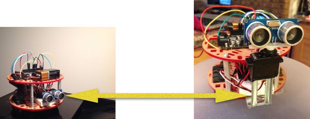
Below is the code that we used to test that the servo would move the ultrasonic sensor from the 90 degree to: 180, 135, 45, and 0 positions. Once again, a library had to be included at the beginning of the code to run the servo motor.
#include Servo.h  //Angle brackets required.

Servo head;

void setup() {
head.attach(9);
head.write(90);
delay(1000);
}

void loop() {
head.write(90);
delay(1000);
head.write(45);
delay(1000);
head.write(0);
delay(1000);
head.write(45);
delay(1000);
head.write(90);
delay(1000);
head.write(135);
delay(1000);
head.write(180);
delay(1000);
head.write(135);
delay(1000);
}
Finally, it was time to pull all the code together. This proved to be the most challenging part of the project in many respects. We found some code which seemed to accomplish most of the functions we were interested in, but also, it had functions we didn’t want. Finding the perfect copy and paste solution wasn’t happening for us. We started by removing some code, and then adding other code that would be required, and testing, and repeating. For 2 months we remained unhappy with the results. Finally, last weekend, we found code from Jaidyn Edwards. We tweaked the ifs and elses, subtracted and added functions for motors, and the pinger’s servo, and Yeah! The code below meets our OAR objectives as of March 6, 2016.
#include Servo.h     //Angle brackets required.
#include NewPing.h   //Angle brackets required.

// Added Right DC Motor
const int motorR1 = 6;
const int motorR2 = 7;

// Added Left DC Motor
const int motorL1 = 4;
const int motorL2 = 5;

// Removed Servo leftServo;       //Create Left Servo object
// Removed Servo rightServo;      //Create Right Servo object

#define TRIGGER_PIN  12   //Trigger pin of Ultrasonic sensor connected to pin 6
#define ECHO_PIN     11   //Echo pin of Ultrasonic sensor connected to pin 7
#define MAX_DISTANCE 400 //The maximum distance we want the sensor to look for is 1m

NewPing sonar(TRIGGER_PIN, ECHO_PIN, MAX_DISTANCE);  //Create Ultrasonic sensor object
Servo head;

unsigned int time;            //Variable to store how long it takes for the ultrasonic wave to come back
int distance;                 //Variable to store the distance calculated from the sensor
int triggerDistance = 20;     //The distance we want the robot to look for a new path
int fDistance;                //Variable to store the distance in front of the robot
int lDistance;                //Variable to store the distance on the left side of the robot
int rDistance;                //Variable to store the distance on the right side of the robot

void setup() {
/* Removed
 * {
  leftServo.attach(9);        //Left servo connected to pin 9
  leftServo.write(90);        //Write the neutral position to that servo
  rightServo.attach(8);       //Right servo connected to pin 8
  rightServo.write(90);       //Write the neutral position to that servo
} */
// Added Servo functionality
  head.attach(9);
  head.write(90);

// Added motor initialization
  pinMode(motorR1, OUTPUT);
  pinMode(motorR2, OUTPUT);
  pinMode(motorL1, OUTPUT);
  pinMode(motorL2, OUTPUT);

// Added motor initialization
  digitalWrite(motorR1, LOW);
  digitalWrite(motorR2, LOW);
  digitalWrite(motorL1, LOW);
  digitalWrite(motorL2, LOW);
}

void loop()
{
  scan();                                //Get the distance retrieved
  fDistance = distance;                  //Set that distance to the front distance
  if(fDistance < triggerDistance){       //If there is something closer than 30cm in front of us
    moveBackward();                      // motor Move Backward for a second
    delay(50);
    moveStop();
    head.write(0);                       // Added Servo turn Right
    scan();
    delay(500);                          // Take a reading
    rDistance = distance;                // Store that to the distance on the right side
    head.write(180);                     // Added Servo Turn left
    scan();
    delay(500);                          // Take a reading
    lDistance = distance;                // Store that to the distance on the left side
    head.write(90);                      // Added return servo to 90 degree position
    if(lDistance < rDistance){           // If the distance on the left is smaller than that of the right
      moveRight();                       // Move right for a quarter of a second
      delay(250);
      moveForward();                     //Then move forward
    }
    else {
      moveLeft();                       // Added the motor Move left
      delay(250);
      moveForward();                     //If the left side is larger than the right side move forward
    }
  }
  else{
    moveForward();                       //If there is nothing infront of the robot move forward
  }
}

void scan(){
  time = sonar.ping();                  //Send out a ping and store the time it took for it to come back in the time variable
  distance = time / US_ROUNDTRIP_CM;    //Convert that time into a distance
  if(distance == 0){                    //If no ping was recieved
    distance = 100;                     //Set the distance to max
  }
  delay(10);
}

/* Removed
 * void moveBackward(){
  rightServo.write(180);
  leftServo.write(0);
}*/

/*void moveForward(){
  rightServo.write(0);
  leftServo.write(180);
}*/

/*void moveRight(){
  rightServo.write(0);
  leftServo.write(0);
}*/

/*void moveLeft(){
  rightServo.write(180);
  leftServo.write(180);
}*/

/*void moveStop(){
  rightServo.write(90);
  leftServo.write(95);
}*/

// Added motors go forward
void moveForward(){
  digitalWrite(motorR1, HIGH);
  digitalWrite(motorR2, LOW);
  digitalWrite(motorL1, HIGH);
  digitalWrite(motorL2, LOW);
  }

// Added motors go backward
void moveBackward(){
  digitalWrite(motorR1, LOW);
  digitalWrite(motorR2, HIGH);
  digitalWrite(motorL1, LOW);
  digitalWrite(motorL2, HIGH);
  }

// Added motors stop
void moveStop(){
  digitalWrite(motorR1, LOW);
  digitalWrite(motorR2, LOW);
  digitalWrite(motorL1, LOW);
  digitalWrite(motorL2, LOW);
  }

// Added motors left turn
void moveLeft(){
  digitalWrite(motorR1, HIGH);
  digitalWrite(motorR2, LOW);
  digitalWrite(motorL1, LOW);
  digitalWrite(motorL2, HIGH);
  }

// Added motors right turn
void moveRight(){
  digitalWrite(motorR1, LOW);
  digitalWrite(motorR2, HIGH);
  digitalWrite(motorL1, HIGH);
  digitalWrite(motorL2, LOW);
  }
Here is some video, taken during one of our tests in January.
